


The Khronos Group recently released a set of provisitional extensions adding video encoding and decoding capabilities to the Vulkan API, collectively referred to as Vulkan Video. This thus seemed like the perfect opportunity to provide an introduction to video compression from the perspective of a graphics programmer, and discuss why having integrated support for video encoding and decoding as part of the Vulkan API is an important step forward for the industry.
DISCLAIMER: This article aims to provide only a rudimental presentation of the basic concepts one needs to be familiar with when working with video codec APIs, targeting developers coming from the graphics rendering world without prior experience with these, and as such some of the simplistic descriptions may cause experts to raise their eyebrows, rightfully so. Nonetheless, the article hopefully covers the foundations in sufficient depth for readers to be able to get started with video encoding and decoding.
Support for compressed video capture and playback became such a basic feature of any interactive computer system that nowadays one hardly finds one that has no support for it. It’s also clear that such systems need dedicated acceleration hardware to be able meet the performance requirements imposed by the ever increasing resolution and frame rate needs. Thus contemporary dedicated GPUs, many CPUs, and most mobile and embedded SoCs come with such dedicated video codec hardware.
Throughout the last couple of decades a large number of video and media codec APIs emerged (then most disappeared) that aimed to provide access to these acceleration engines at different abstraction levels. However, most of these APIs were or still are either hardware vendor or platform dependent, and a few that came with wider portability promises couldn’t really live up to those due to lack of adoption by the industry players. While Vulkan Video is yet to prove that it could overcome this “curse” haunting these APIs, the momentum of the Vulkan API in general should certainly help in this respect.
Arguably, another aspect of many of the existing video codec API standards and libraries that concern developers targeting high performance interoperability between video encode/decode and rendering, is that many lack copy-less sharing of frame data and/or efficient synchronization at sharing boundaries, as they were designed around a similar CPU-centric model as legacy graphics APIs did, which often results in additional transfer or synchronization round-trips between the GPU and the CPU. The few APIs that do provide efficient sharing are often limited to particular hardware vendors, platforms, or to specific use cases e.g. efficient presentation to screen. Taking advantage of the explicit memory management and synchronization infrastructure offered by the core Vulkan API, Vulkan Video should be able to overcome these obstacles.
In order to accentuate the importance of efficient video and rendering interop, it’s worth mentioning a couple of typical use cases:
- Video texturing – i.e. being able to use compressed videos as a streaming source for texture data mapped onto 3D geometry (quite common in video games, but desktop compositors can similarly benefit, and use cases generally have high efficiency requirements)
- Streaming renderers – i.e. being able to efficiently stream the output of rendering applications to other applications or remote devices (for interactive use cases latency is of key importance)
- Video post-processing – e.g. being able to apply GPU based filters on a series of compressed video frames
- Video periferal support – e.g. using IP camera input
The anatomy of compressed video
Generally speaking, a compressed video stream consists of a bitstream that contains a (typically lossy) compressed representation of each image frame of the video sequence with some additional codec specific metadata (e.g. parameter sets) that is necessary for a decoder to be able interpret the compressed data and display the decompressed images.
In the simplest case each frame of the video is compressed separately, e.g. one can create a compressed video stream out of a series of JPEG compressed images. Such a compressed frame of a complete image is called an I-frame (intra-coded frame), sometimes referred to as a keyframe, although the application of the latter term is rather context specific.
NOTE: While the terms "frame" and "picture" are often used interchangeably, video compression algorithms usually work in terms of pictures which can represent either a frame or a field. Fields are used in case of interlaced video where pairs of subsequent fields comprise a full frame, one holding the odd-numbered scanlines and the other holding the even-numbered scanlines. We will use the term "frame" throughout the article because it is the more common terminology used in literature, but usually we actually mean a "picture".
Of course, the quality/bitrate metrics of modern video codecs wouldn’t be achievable if all images would be individually compressed into I-frames, as those only take advantage of spacial coherency of pixel data. Instead, temporal coherency is leveraged by usually only storing compressed differences between separate image frames of the video.
A P-frame (predicted frame), sometimes referred to as a delta-frame or inter-frame, encodes only changes compared to an earlier frame. The frame that is used to calculate the delta-frame from is called the reference frame (or reference picture). While commonly this difference is calculated with respect to the immediately preceding frame, P-frames can refer to any earlier frame in the general case. In fact some codecs may also allow using multiple reference frames together with the image frame to construct a P-frame.
Even higher compression rates can be achieved when compressing an image frame as a B-frame (bidirectional predicted frame) as this frame type allows a delta-frame to refer not only to earlier frames in the sequence, but also later ones. Once again, typically B-frames are encoded using the immediately preceding and the subsequent frames as references, but this isn’t always the case.
It’s also worth noting that the reference frames used by a P- or B-frame themselves may be delta/predicted frames, they don’t have to be I-frames.
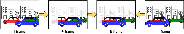
Note how the B-frame can take advantage of image information from both the preceding and subsequent frames used as reference frames.
The order in which I-, P-, and B-frames follow each other in the video sequence is called the GOP (group of pictures), and some decoder/encoder implementations may require the GOP to have a specific size (number of pictures/frames) or structure (order in which different picture/frame types follow each other). The GOP structure is often described by two numbers, telling the distance between subsequent P and I frames, respectively, e.g. a GOP with M=3, N=9 means that its structure is IBBPBBPBBI, where each letter refers to a corresponding frame type in the sequence.
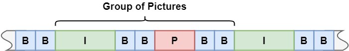
NOTE: actual physical order of frames in the bitstream is usually different, as discussed later.
NOTE: Some codecs also support the compression scheme to be controlled at a finer granularity. These are typically rectanglar sub-regions splitting the picture horizontally or vertically. E.g. H.264/AVC calls these slices, and a single frame may contain different types of slices (I-slices, P-slices, B-slices).
The basic processing unit of video codecs varies, however, it’s quite common to use some sort of block-based coding. E.g. H.264/AVC uses 4×4, 8×8, or 16×16 pixel sized macroblocks (MB) and H.265/HEVC uses 16×16 or 64×64 pixel sized coding tree units (CTU). The encoding process usually uses techniques like motion estimation to select picture segments to produce delta information from and the image data (or image difference data) is compressed using discrete cosine transform, Huffman coding, run-length encoding, or other algorithms specific to the particular codec, including appropriate quantization at certain levels of the process to achieve the desired quality-to-size ratio.
Inputs and outputs
The actual uncompressed frame format used as the source for video encoding and the destination of video decoding varies between codecs and implementations, but typically they use images in a YCbCr color space, i.e. a format with a luminance (luma) and two chrominance (chroma) channels.
NOTE: Going forward we will use the terms YCbCr and YUV interchangeably. Strictly speaking, this is inaccurate as YUV refers to an analog encoding scheme, nonetheless it's quite common for literature to refer to YCbCr formats as YUV formats, the U and V channels being equivalent to the Cb (blue chrominance) and Cr (red chrominance) channels, respectively.
Often chrominance is stored at a lower resolution. This practice is called chroma subsampling, and it means that chrominance samples may be shared among several luminance samples. The particular chroma subsampling scheme used is commonly expressed as a three-part ratio J:a:b, where:
- J is the horizontal sampling reference (i.e. the horizontal region width in pixels in terms of which the chroma to luma ratio is expressed) and usually has the value 4
- a is the number of chrominance samples, including both Cr and Cb samples, across the horizontal sampling reference (i.e. per rows of J pixels)
- b is the row stride in terms of chrominance samples (i.e. the index of the first chrominance sample pair in the second row of J pixels), which is zero for formats with only a single row of chrominance samples
Some YUV formats include an alpha channel as well in which case a fourth value is included in the ratio, although the alpha sampling rate always matches the luma sampling rate (J) in these cases.

Another thing to keep in mind when working with YUV formats using chroma subsampling is that the mapping between luma and chroma values, i.e. the points at which luma and chroma samples were “measured” on the original full resolution image can be ambiguous without further contextual information. In order words, the image-space coordinates of luma samples and corresponding chroma samples may not coincede. Thus the interpretation of chroma subsampled YUV formats require knowing the relative location of luma and chroma samples.
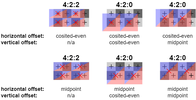
NOTE: the coordinate space convention used has a lower-left origin.
From the perspective of in-memory representation, we distinguish between packed and planar YUV formats. Packed formats interleave luminance and chrominance samples, while planar formats use separate planes for luminance and chrominance, sometimes even separate planes for red and blue chrominance. Some literature calls the latter as fully planar format compared to semi-planar formats that include both Cr and Cb in a single plane. In addition, certain YUV format definitions also require specific placement of the individual planes of planar YUV formats in memory.

GPUs usually come with support for accessing YUV formatted images/textures, however, the level and type of support can vary.
Some GPUs and corresponding driver implementations limit support to being able to access the raw YUV format itself (i.e. access the luminance and chrominance values), allowing creating textures with YUV formats, and being able to read from, write to and sample from (with filtering) these images/textures.
In case of packed 4:4:4 formats this works similarly to RGB/RGBA formats, except that the semantics of the individual channels are different. For some subsampled packed formats (e.g. UYVY) a single texel value can actually include more than one luma samples each in a different channel.
Planar YUV formatted textures work similarly to planar depth/stencil textures whereas the actual texture consists of multiple planes, sometimes having different resolutions as well due to chroma subsampling, and shader access (or other type of GPU access) is allowed to them on a per-plane basis.
Other GPU and/or driver implementations, instead or as an alternative, allow addressing and interpreting YUV formatted textures in other ways. E.g. some implementations may allow sampling from planar YUV formatted textures through a single sampler resource variable in the shader, and some may even support a fixed set of YCbCr-to-RGB conversion modes meaning that the texel values get converted between the corresponding color spaces, thus sampling instructions producing RGB result values. This may be made possible either through dedicated hardware support for multi-plane access and color-space conversion, or through software emulation which enable the driver to mimic hardware support by manually converting YUV texture sample operations into per-plane native access operations complemented with in-shader filtering and color space conversion.
Vulkan exposes support for these functionalities through the VK_KHR_sampler_ycbcr_conversion extension that is part of the core API in Vulkan 1.1. The name itself is a bit misleading when one considers that native hardware support varies across implementations, however, Vulkan provides the necessary tools to perform either raw per-plane access (through the creation of per-plane image views), or multi-plane access with or without color space conversion (through the use of samplers with YCbCr conversion enabled), although support for each is not uniform across driver implementations for the reasons mentioned above.
| Vulkan format | Known YUV format names | Bits / channel | Chroma subsampling | Layout type | Bits / pixel |
|---|---|---|---|---|---|
| R8G8B8A8_UNORM | AYUV[1] | 8 | 4:4:4 | Packed | 32 |
| G8_B8_R8_3PLANE_444_UNORM | YV42[2]/YV24[1,2] | 8 | 4:4:4 | Planar | 24 |
| B8G8R8G8_422_UNORM G8B8G8R8_422_UNORM | UYVY/VYUY[1] YUY2/YVYU[1] | 8 8 | 4:2:2 | Packed | 16[3] |
| G8_B8R8_2PLANE_422_UNORM | NV16[2]/NV61[1,2] | 8 | 4:2:2 | Semi-planar | 16 |
| G8_B8_R8_3PLANE_422_UNORM | YV61[2]/YV16[1,2] | 8 | 4:2:2 | Planar | 16 |
| G8_B8R8_2PLANE_420_UNORM | NV12[2]/NV21[1,2] | 8 | 4:2:0 | Semi-planar | 12 |
| G8_B8_R8_3PLANE_420_UNORM | YV21[2]/YV12[1,2] | 8 | 4:2:0 | Planar | 12 |
| G10X6_B10X6_R10X6_3PLANE_444_UNORM_3PACK16 G12X4_B12X4_R12X4_3PLANE_444_UNORM_3PACK16 G16_B16_R16_3PLANE_444_UNORM | ?[1] ?[1] ?[1] | 10 12 16 | 4:4:4 | Planar | 48 |
| R10X6G10X6B10X6A10X6_UNORM_4PACK16 R12X4G12X4B12X4A12X4_UNORM_4PACK16 R16G16B16A16_UNORM | ? ? ? | 10 12 16 | 4:4:4 | Packed | 64 |
| B10X6G10X6R10X6G10X6_422_UNORM_4PACK16 G10X6B10X6G10X6R10X6_422_UNORM_4PACK16 B12X4G12X4R12X4G12X4_422_UNORM_4PACK16 G12X4B12X4G12X4R12X4_422_UNORM_4PACK16 B16G16R16G16_422_UNORM G16B16G16R16_422_UNORM | UYVP/VYUP[1] YUYP/YVYP[1] ? ? ? ? | 10 10 12 12 16 16 | 4:2:2 | Packed | 32[3] |
| G10X6_B10X6R10X6_2PLANE_422_UNORM_3PACK16 G12X4_B12X4R12X4_2PLANE_422_UNORM_3PACK16 G16_B16R16_2PLANE_422_UNORM | ? ? ? | 10 12 16 | 4:2:2 | Semi-planar | 32 |
| G10X6_B10X6_R10X6_3PLANE_422_UNORM_3PACK16 G12X4_B12X4_R12X4_3PLANE_422_UNORM_3PACK16 G16_B16_R16_3PLANE_422_UNORM | ? ? ? | 10 12 16 | 4:2:2 | Planar | 32 |
| G10X6_B10X6R10X6_2PLANE_420_UNORM_3PACK16 G12X4_B12X4R12X4_2PLANE_420_UNORM_3PACK16 G16_B16R16_2PLANE_420_UNORM | ? ? ? | 10 12 16 | 4:2:0 | Semi-planar | 24 |
| G10X6_B10X6_R10X6_3PLANE_420_UNORM_3PACK16 G12X4_B12X4_R12X4_3PLANE_420_UNORM_3PACK16 G16_B16_R16_3PLANE_420_UNORM | ? ? ? | 10 12 16 | 4:2:0 | Planar | 24 |
[1] Requires appropriate channel swizzle
[2] Depends on whether the implementation uses a contiguous representation
[3] Contains two pixels per texel, i.e. two luma samples per texel
Due to the limited set of color space conversion presets supported by the hardware/driver/API, it’s quite likely that any Vulkan based library or application that needs to handle arbitrary YCbCr data will need to use raw per-plane YUV texture access in the general case, as that allows supporting arbitrary types of YCbCr and RGB color spaces. Nonetheless, developers should consider adding fast-paths to their products using the built-in YCbCr conversion samplers where support is available, especially in power or performance constrained systems like mobile devices.
Encoding and decoding process
The toolset of a complete video codec is usually extremely wide, both in terms of the set of supported input/output frame formats, the method used to encode/decode those, etc. As such, usually video codec standards define multiple profiles that mandate certain capabilities, targeting specific classes of applications. In addition, video codec standards usually also define a set of levels that define corresponding decoder performance requirements (e.g. sample rate or bit rate). Video decoder implementations need to support the specific profile a compressed video was encoded with in order to be able to decode it, and need to support a specific level to be able to decode the video in real-time.
The encoder side of things is less constrained and uniform. While the specific codec, profile, and level limit the set of compression and encoding schemes available, individual encoder implementations, let those be software or hardware encoders, may use different techniques and algorithms to produce a conforming bitstream. In particular, fitting within a particular bit rate budget either contrained by the target codec profile level or by the storage/transmission limits is typically controlled using vendor or implementation specific configuration commands and parameters. These mechanisms are collectively referred to as rate control and have a direct effect on the achieved compression rate, visual quality, and performance on a given encoder implementation.
Both the encoding and decoding process employs a special resource pool called the decoded picture buffer (DPB). This pool stores the reference pictures (usually frames) used during the encoding and decoding of P-frames and B-frames. As discussed earlier, depending on the codec and implementation, individual P-frames and B-frames may refer to more than one reference frame, and they may each use different frames as their reference, hence in the general case the DPB needs to be able to hold more than just a single reference picture. The codecs (and individual profiles within it) generally define an upper bound on the DPB capacity.
A frame/picture is added to the DPB if it planned to be used as a reference frame of a subsequently encoded or decoded frame, and is later removed from the DPB when no further frames need to refer to it anymore. Thus the DPB is a container for transient image data needed during the encoding and decoding process.
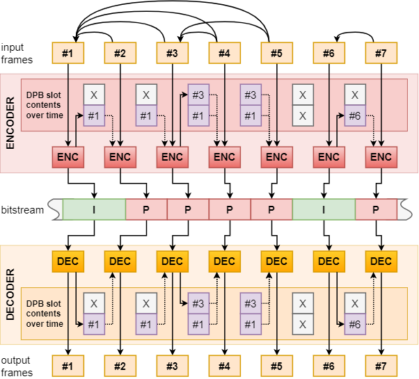
Adding reference frames to the DPB is trivial during decoding: when decoding a frame that is marked as a reference frame the decoder simply adds the output of the frame decoding to the DPB, either by reference or by copy. During encoding, however, we cannot simply use the original incoming image frame data as the reference frame, at least not in case of lossy compression schemes (which is usually the case with video codecs). If we would do so, then we would construct the delta-frame based on the original image frame which is not known to the decoder, thus decompressing the delta-frame would have different (incorrect) results.
Instead, when encoding a frame that is marked as a reference frame the encoder will reconstruct the frame from the output of the frame encoding and add this reconstructed frame to the DPB. This is also the reason behind why the DPB is often also referred to as the reconstructed picture buffer in the context of video encoding.
It’s worth noting here though that this frame reconstruction process does not necessarily require decompressing the bitstream resulting from the frame encoding, as usually encoders can simply generate the reconstructed frame from the original input image frame and internal data collected during the encoding process. Nonetheless, due to the reconstructed frame being generally different compared to the input image frame, adding a reference frame to the DPB during encoding requires a copy.
As the reference frames need to be available at the time a P-frame or B-frame referring to them is encoded or decoded, frames used as reference frames always need to be encoded/decoded before any dependent frames. This is a given in case of a simple encoder or decoder that simply processes subsequent frames in the video sequence one after another, however, due to the nature of B-frames which may use “future” frames as references, such a scheme cannot work in the general case.
The concequence of that is that we need to distinguish between coding order, i.e. the order in which we encode/decode individual frames/pictures/slices to/from the bitstream, and display order, i.e. the order in which the frames are expected to be presented during video playback. In the simple cases the two orders match, but when using B-frames the two diverge.
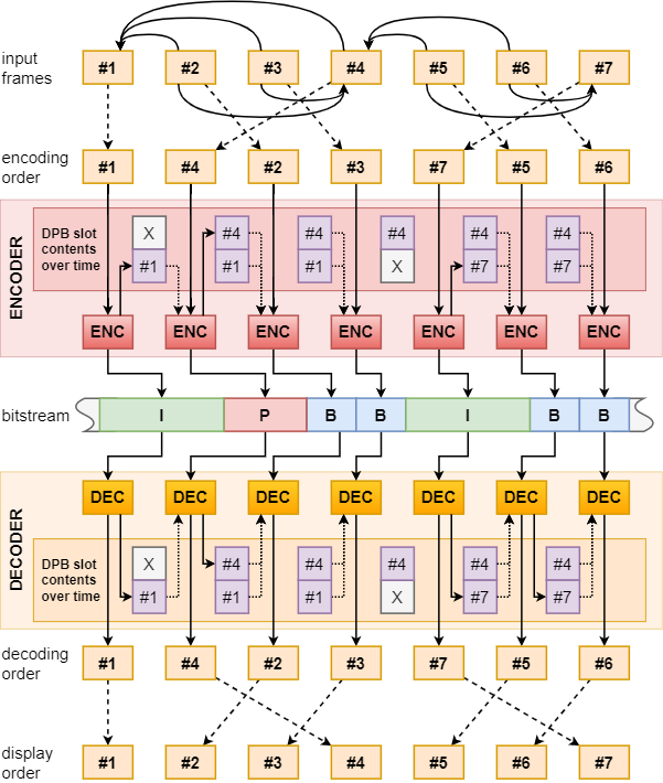
Note how frames used as backward (future) references are encoded and decoded before the dependent B-frames.
As the presence of B-frames may have an effect on the latency between decoding and presentation of video frames, often codec profiles also define restrictions on the use of them, and decoder implementations have to be designed with this potential latency in mind.
Quite often events like data corruption or transmission errors may result in the inability to process certain parts of the incoming bitstream which may leave the DPB in an inconsistent state. This can cause decompression failures/artifacts in case of P- and B-frames that refer to reference frames that were “lost” due to such events. Eventually the effect of such failure events go away once no new incoming frame arrives that refer to these lost reference frames and the DPB’s reference frame slots get replaced with new references.
Some codecs also define a special I-frame type called an IDR-frame (instantaneous decoder refresh frame) that, in addition to being intra-coded, also clears the contents of the DPB. That means all subsequent frames/pictures/slices are guaranteed to not refer to any frame decoded prior to the IDR-frame. This feature also makes seeking video streams easier and more responsive as the player can know for sure that it can safely start processing a stream at IDR-frame boundaries without caring about earlier bitstream data.
The new kid on the block
When it comes to hardware acceleration, most implementations focus strictly on image data processing with limited or no handling of metadata (codec parameter sets, etc.), as the actual image data compression/decompression is the most computationally intensive part of the process. Accordingly, producing a complete conformant bitstream out of the encoded frames, packaging them in any particular storage format, and, similarly, consuming those typically necessitates additional code around the use of the hardware accelerator or the use of 3rd party libraries designed for this purpose.
Vulkan Video exposes video encoding and decoding functionality through a series of extensions:
- VK_KHR_video_queue provides the common infrastructure for video codec support
- VK_KHR_video_encode_queue provides the encode specific APIs
- VK_KHR_video_decode_queue provides the decode specific APIs
- Additional encode and decode extensions provide the codec specific parts
These extensions provide direct access to the actually hardware accelerated parts of the video encode/decode process, offering explicit control over the following:
- Issuing individual encode/decode operations on pictures with specific picture/slice types
- Controlling the contents of the DPB, i.e. marking a picture as reference and specifying the references used by predicted pictures
- Managing the rate control parameters used during video encoding
- Video session objects providing a context for the often stateful encoding/decoding process, that enables handling multiple video streams in parallel or in an interleaved fashion
The programming model itself should be sufficiently familiar to developers accustomed to the rest of the Vulkan API. Video codec functionality is exposed through a set of new queue families with video encode and/or decode capabilities. Individual picture encode and decode operations are recorded in coding order into command buffers enqueueable to a queue of the appropriate queue family, with memory backing, resource management (e.g. image layout transitions), and synchronization being handled with the usual Vulkan mechanisms.
The provisional extension specifications still have some rough edges and certain under-specified behaviors, but considering their status and the fact that this is a major feature from a quite different domain than what graphics API design usually concerns with, it’s big news to have them available for public evaluation.
For those interested, NVIDIA already offers beta drivers with support for the provisional Vulkan Video extensions, and they even published an open-source video decode sample that, while still being largely work-in-progress as of the time of writing this article, should provide sufficient material for developers to get started with the API.