


There are numerous misconceptions out there about Vulkan memory barriers and image layout transitions to the extent that even the most seasoned developers get certain details wrong about them. This article aims to clear up these misconceptions by delving into the details of the motivation and behavior behind these operations while also covering when and how to use them in practice.
Since the advent of the new generation of low-level / explicit graphics APIs such as Vulkan, developers are struggling with comprehending and correctly using pipeline barriers and it is often cited as the most difficult element of these new APIs. At the time of writing, these APIs have already been with us for a decade, yet there are still many aspects of them that are misinterpreted by developers. Misusing them can result in rendering corruption, in performance issues, or both, and the difficulty in getting them right is that the symptoms of incorrect use may vary across hardware, even between GPU generations or models of the same vendor.
Over the years, these APIs also evolved a bit: some graphics APIs took ideas from others to leverage performance optimization opportunities unavailable before, specifications provided more accurate and concise descriptions, new versions of the APIs attempted to make them simpler and easier to understand. There are even initiatives that seek to sacrifice certain aspects of the control available to the developers on the altar of simplicity, such as the VK_KHR_unified_image_layouts extension that aims to (more or less) “deprecate” the need for image layout transitions.
These developments also reflect the fact that hardware implementations have converged and evolved since the conception of these new generation of graphics APIs, but, as we will see as we explore the problem space in this article, the fundamental principles and motivation behind these seemingly complex API concepts remain to have relevance today and are unlikely to ever go away completely.
Throughout the article, we will use AMD’s original GCN architecture as an example, as it is a well known and thoroughly documented GPU architecture that also happens to be able to take advantage of pretty much all aspects of the pipeline barrier design of Vulkan. While nowadays these GPUs can be thought of as archaic, the conceptual model still applies today to a wide range of hardware, even outside the world of GPUs.
Having made significant contributions to the original design of the Vulkan pipeline barrier APIs, hopefully, the article also provides additional insight into the motivation of certain design choices.
What is a pipeline barrier?
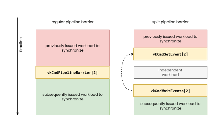
When we talk about pipeline barriers we mean the operations issued by the command buffer commands such as vkCmdPipelineBarrier[2], and their split variants comprising of pairs of vkCmdSetEvent[2] and vkCmdWaitEvents[2] calls. These operations enable expressing dependencies between subsequently issued action commands such as draws, compute dispatches, ray tracing, video coding operations, etc.
The need for the application developer to have to specify such dependencies is more or less a new requirement of the new generation of graphics APIs, but the need for them from a hardware perspective has been there much earlier. Due to the quasi-synchronous execution model of legacy APIs, such as OpenGL, such dependency information could not be specified, therefore it was the driver’s responsibility to automatically insert them behind the scenes. This is referred to as “implicit synchronization”, although in some cases even legacy APIs employed explicit synchronization operations in newer API features (see glMemoryBarrier as an example).
The problem with implicit synchronization is that the driver does not always have all the contextual knowledge to be able to identify the dependencies or minimize the necessary synchronization cost. This often results in the driver having to make conservative decisions about when and what type of pipeline barrier to insert and that typically results in suboptimal performance. This performance cost can range from less than 1% to over 50%, depending on the application, hardware, and driver. Furthermore, in an attempt to optimize these cases, drivers of legacy APIs usually employ heuristics that often lead to unexpected performance cliffs. Explicit synchronization therefore provides additional optimization tools to the developer and delivers more predictable performance characteristics at the cost of some application complexity.
It is also worth noting the effects of modern “bindless” and GPU-driven techniques from the perspective of synchronization. Implicit synchronization was only an option in legacy APIs because the APIs had exact, trackable points where a resource was bound to a specific use, therefore the driver could reason about when two uses of the same resource may need synchronization. With the advent of “bindless” resources and GPU-driven workload submission, the driver doesn’t even stand a chance and may have to resort to even more conservative synchronization choices with even higher unnecessary performance overhead.
A pipeline barrier can be thought of as the combination of the following:
- Execution control – defines the set of previously issued work that needs to be waited on to complete before subsequently issued work can start
- Cache control – provides a way to flush and/or invalidate caches in order to make sure that subsequently issued work has a coherent view of shared data
- Image layout transitions – we will discuss these later in detail, in short, they allow transforming the internal representation of images (textures) for specific use
These are more or less orthogonal aspects of a pipeline barrier and, depending on the hardware implementation, it may be possible to issue them completely independently, but bundling them into a single operation enables better portability across hardware architectures, as hardware often performs them in tandem (particularly execution and cache control) while also enabling driver optimization opportunities (by coalescing operations).
Since VK_KHR_synchronization2 and Vulkan 1.3, there is no longer such a clear separation between execution control and cache control, as the new APIs express execution dependencies as part of the memory barriers, but we keep our discussion focused on the way the pipeline barrier design was originally conceived and discuss them separately. While the new, combined view of the two aspects of pipeline barriers makes it somewhat easier to reason about formally, the separate view of the two better showcase what actually happens on the underlying hardware.
Execution control
While the focus of this article is the topic of memory barriers and the related image layout transitions, it is worth having a few words about execution control, i.e. the so-called “happens-before” and “happens-after” relationships.
Execution control is the main moving force of pipeline barriers. As the purpose of pipeline barriers is to define a dependency between two sets of work items, this aspect plays a key role by providing information about those.
In Vulkan, execution control is specified in the form of two sets of pipeline stage masks. The execution dependency will cause the hardware to wait for all previous workloads to complete all their work in the specified set of source pipeline stages before the processing of subsequent workloads starts in the destination pipeline stages. Vulkan defines a fine grained set of pipeline stage flags enabling the application to specify the exact point within the graphics (or other type of) pipeline that has to be waited on and where the wait has to happen at the latest.
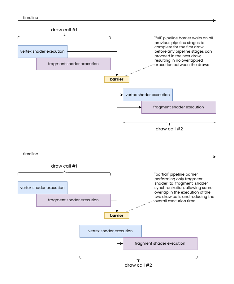
The “full” pipeline barrier synchronizes all previous pipeline stages with all subsequent ones.
The “partial” pipeline barrier only synchronizes fragment shader stages.
Note how the latter allows for overlapping execution of shader stage workloads from different draw calls therefore resulting in a shorter overall execution time.
In practice, hardware does not necessarily have the same level of granularity. For example, some hardware may not be able to wait only on the completion of fragment shaders without also having to wait on the completion of color attachment outputs. Also, on the waiting side, some hardware may not be able to start the vertex processing and rasterization of subsequent work even if the wait is supposed to only block fragment shaders. Nonetheless, the application should specify fine grained information whenever possible as even if those do not provide any performance benefits on one GPU they may provide a significant performance boost on another. The benefits can grow as hardware and drivers evolve.
In case of the original GCN architecture, as an example, waiting was only possible inside the command processor, therefore typically (with some exceptions) all pipeline stages of all subsequent commands were blocked by the pipeline barrier, no matter the specified set of destination pipeline stage flags, but work completion signaling had some level of granularity, such as waiting on all vertex processing work and waiting on fragment shader completion. Newer hardware, however, supports finer granularity for execution control.
While this may sound overly verbose, this granularity for execution control enables significant optimization opportunities compared to legacy APIs where the implementation often had to resort to fully draining the pipeline before proceeding with subsequent work, resulting in the so-called “pipeline bubbles”. In fact, there are cases where even this fine granularity is not sufficient, for example, waiting on or before transfer operations may still result in unexpected dependencies as some transfer operations may not be implemented using dedicated DMA operations but through issuing driver-internal graphics or compute pipelines. This could have been solved by the API exposing what method of execution a particular transfer operation uses, but that would further increase the complexity of the API that many developers already deem too complex.
Cache control
We already discussed in great detail in our earlier article (Understanding GPU caches) that GPUs usually employ non-coherent cache hierarchies to boost performance compared to CPUs where the coherent cache hierarchies, while providing a convenient programming model, incur inherent die area and performance costs despite having relatively small number of threads stomping on shared data compared to GPUs. Therefore, execution control alone is rarely sufficient and cache control operations are necessary in almost all cases in order to ensure a coherent view of data in memory across subsequently issued operations.
In a nutshell, while GPUs usually feature at least one device-wide cache that is shared by, and therefore provides coherent access for, all or at least most processing units of the GPU, most processing units (shader cores, ROPs, etc.) have their own private, non-coherent caches that may need to be flushed and/or invalidated in order to share a consistent view of the underlying data across those units. These are the operations formally referred to making the results of memory writes “available” and “visible”, respectively.
We generally distinguish between three types of cache coherency related data hazards:
- Read-after-write (RAW) – when writes of previous operations may not have completed before subsequent operations attempting to read the result of those, potentially causing subsequent operations to read stale data and misbehave
- Write-after-read (WAR) – when writes of subsequent operations may overwrite data that is yet to be be read by previous operations, therefore potentially causing previous operations to misbehave
- Write-after-write (WAW) – when writes of previous operations may not have completed before writes of subsequent operations, potentially producing unexpected results in the end
It is worth noting that, depending on the application, memory access hazards do not necessarily cause problems. For example, if the relative order of multiple writes does not matter, a WAW hazard could be ignored, and if it’s okay for reads to read stale (not the most up-to-date) data, then RAW hazards could be ignored. However, these are rare, niche cases, and typically applications expect consistent behavior and coherent accesses.
Cache control is expressed in Vulkan pipeline barriers in the form of memory barriers specifying two sets of access masks. These specify the source access types performed by previous operations that need to be synchronized with the destination access types performed by subsequent operations. In the second version of the synchronization APIs introduced by the VK_KHR_synchronization2 extension and promoted to core in Vulkan 1.3, the access masks are always relative to the pipeline stages specified as part of the execution control, therefore more tightly coupling the two. This means that you must always include the pipeline stage flags corresponding to any specified access flag.
The effect of specifying a set of source and destination access masks in a memory barrier therefore can be described as follows:
- the source access mask is mapped to a set of corresponding cache paths (paths within the cache hierarchy serving the corresponding type or types of access)
- the destination access mask is also mapped to a set of corresponding cache paths
- the two sets of cache paths overlap up to some point (up to the most local cache that is shared and therefore coherent across the paths) or otherwise they are completely disjoint, therefore the only coherent view is through memory – this will be the target
- all cache paths corresponding to the source access mask are flushed all the way up to the target cache level or memory
- all cache paths corresponding to the destination access mask are invalidated all the way up to the target cache level or memory
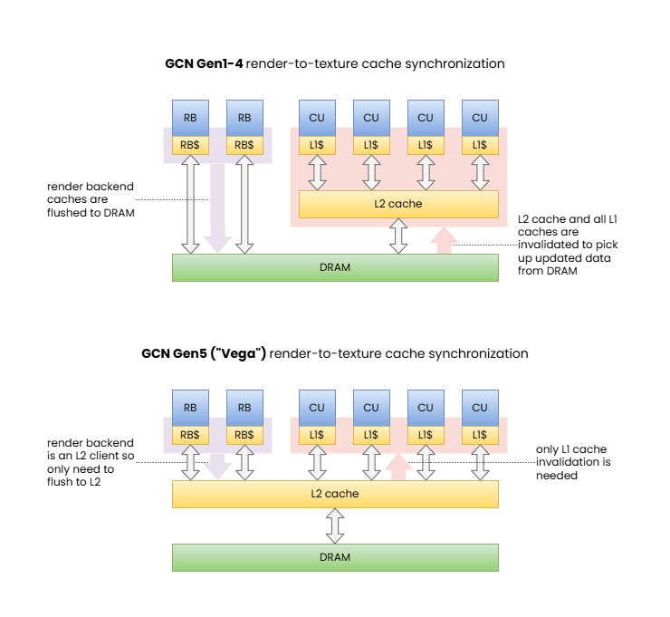
[1] Memory barrier synchronizing color attachment output to shader read.
These diagrams illustrate how the same memory barrier can result in significantly different behavior and performance characteristics on different GPUs.
Note: RDNA is also similar to GCN Gen5 barring the extra cache levels. We included this example to showcase the shift in behavior across GPU generations.
Of course, this description may or may not fully reflect what actually happens on any specific hardware, as implementations may implement all sorts of cache coherency protocols. Furthermore, complete invalidation may be avoidable if the hardware can selectively invalidate only the cache lines that contain data from memory addresses actually updated by the flush. In other words, the effects of a full flush and invalidation can be achieved through applying appropriate coherency protocols directly between the two disjoint cache paths. Although, as with many other details, GPU architectures vary and will use a solution that they deem the best for the purpose, potentially using different policies for different types of caches within the hierarchy, and these details do not have any visible effect on the application other than somewhat varying performance characteristics observed on different implementations, or different types of corruptions when using incorrect pipeline barriers. In the end, everything is a die area, power/energy usage, and performance trade-off.
Another thing to note is that even pipeline barriers can only synchronize access across these non-coherent cache paths at the granularity of entire operations such as two draw calls. Within a single draw, compute dispatch, or other operation, there may still be data hazards. There are various tools to avoid those too in specific cases, such as the OpMemoryBarrier SPIR-V instruction, the Coherent SPIR-V decoration (pre-Vulkan Memory Model), and the Make*Available/Make*Visible SPIR-V operand bits (post-Vulkan Memory Model). While those features are orthogonal to pipeline barriers, the latter ones deserve an example as it has important interactions with pipeline barriers.
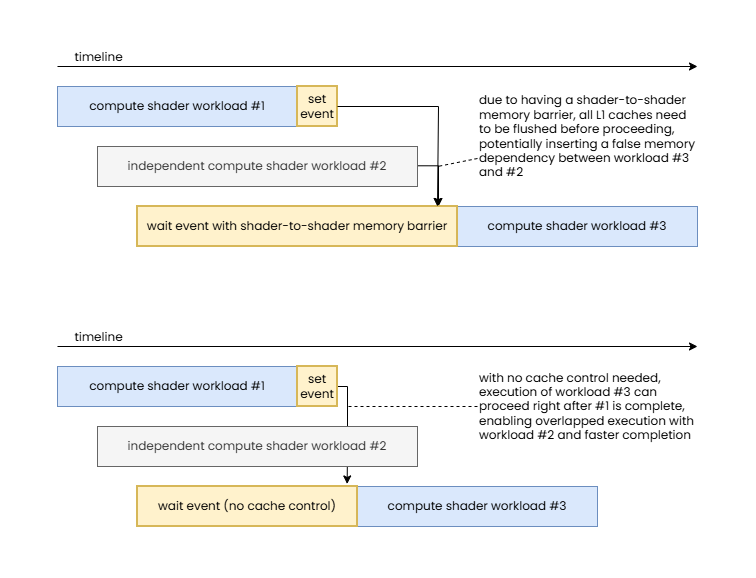
It is quite common in modern workloads to have a set of back-to-back compute dispatches that share data, e.g. earlier compute dispatches writing outputs that are consumed by subsequent ones. A natural way to synchronize such compute dispatches would be with a pipeline barrier that specifies COMPUTE_SHADER_BIT in both the source and destination pipeline stage masks, and SHADER_WRITE_BIT and SHADER_READ_BIT in the source and destination access masks, respectively. However, if the shared resource is marked with the Coherent SPIR-V decoration, then the memory operations themselves will, by definition, be coherent (i.e. they bypass the shader core’s private cache). Similar behavior can be achieved when using the Vulkan Memory Model and the Make*Available/Make*Visible SPIR-V operand bits used with the Device scope.
In this case the source and destination access masks can be left blank in the pipeline barrier and proper synchronization is still ensured while still achieving similar performance, as the shader core private caches rarely show traditional cache reuse behavior due to their small size (as explained in our article about Understanding GPU caches). This approach can provide great optimization opportunities when combined with split barriers comprising of pairs of vkCmdSetEvent[2] and vkCmdWaitEvents[2] calls, as when there is sufficient workload submitted between the dependent compute shaders there may not be a need for any wait to happen (the previous compute shader may already be done) and the entire (execution-control-only) pipeline barrier may turn into a zero-cost operation.
Note how this enables execution to overlap between independent workloads and therefore reduce total execution time.
While driver implementations could implicitly detect in the example above that all the previously executed compute shaders used the Coherent SPIR-V decoration or the Make*Available/Make*Visible SPIR-V operand bits, therefore the SHADER_WRITE_BIT and SHADER_READ_BIT cache control flags could be ignored, there is no guarantee on whether actual driver implementations will do so. Even if they do, they can only make decisions based on static code analysis that inherently limits what the driver may be able to assume.
This use case alone is a great example of why execution control and cache control are separate and why having explicit control over each can be beneficial, but there are other, less common cases where one could take advantage of controlling these two aspects of synchronization separately, particularly, performing execution control without cache control. On a related note, unlike the original synchronization APIs in Vulkan, the variants introduced by VK_KHR_synchronization2 no longer support the other direction: performing cache control without execution control, though this does not limit any practical use cases.
One more interesting aspect of VK_KHR_synchronization2 is that the split version of pipeline barriers now includes the memory dependencies as part of the information passed to vkCmdSetEvent2. In order to understand why the original design did not include that information in the first part of the split barrier, it is worth looking into how they were implemented on the GCN architecture originally (and likely on many other GPU architectures). There, execution control was as simple as signaling the completion of earlier work by asking the hardware to write a value to a memory address (the VkEvent object) once the work is complete that the GPU’s command processor can then wait on later (as discussed earlier, the original GCN could only wait at the “top of the pipe”). The cache control operation itself (both cache flushing and invalidation) was a completely orthogonal operation issued by the command processor afterwards. Therefore, specifying the memory dependencies as part of the signal operation (vkCmdSetEvent) was unnecessary. However, on an implementation that can combine execution control and cache control operations or one that can issue cache flushes separately from cache invalidations, having the information up-front, at the time of signaling the event, enables issuing any necessary cache flushes earlier or otherwise optimizing the process. Therefore the new model isn’t just better from the perspective of the formal model, but can actually provide tangible benefits on a sufficiently sophisticated hardware implementation.
Buffer and image memory barriers
Memory barriers in Vulkan come in three forms:
- Global memory barriers – describe memory barriers that apply to all memory locations
- Buffer memory barriers – describe memory barriers that apply only to memory locations corresponding to the specified buffer range
- Image memory barriers – describe memory barriers that apply only to memory locations corresponding to the specified image subresource range
There are various reasons for the existence of these three separate categories. For example, buffer and image memory barriers can also include queue family ownership transfers and image memory barriers can also include image layout transitions. These will be discussed later in detail. For now we will only focus on the cache control aspect of these.
As the brief descriptions above suggest, the key difference between the three is the range of memory locations the memory barrier applies to. This enables exposing the ability to perform partial/selective cache flush/invalidation operations on hardware implementations that support them. Unlike a full cache flush/invalidation operation, such cache coherency operations can selectively flush/invalidate only a subset of the cache lines in the affected caches that fall into a specific address range while leaving all other cache lines untouched. In our case, these address ranges are provided indirectly through the specified buffer ranges and/or image subresource ranges.
This can have a positive performance effect for accesses of other resources that the memory barriers do not affect as their data is not evicted from the lower-level caches unnecessarily. Unfortunately, not all hardware supports this, and even those that do don’t necessarily have this particular optimization opportunity leveraged in their driver stack. Furthermore, the performance benefits of such optimizations are usually only visible when the cache control operation results in having to flush/invalidate larger caches (like the L2 cache flush/invalidation that was often needed on the original GCN architecture to synchronize framebuffer operations with texturing) as the most local caches are rarely sufficiently large to still have relevant data to be reused from the cache at any given time.
Nonetheless, even though it is an opportunistic optimization that may or may not show any benefits in practice on any given workload, application developers should prefer to use buffer and/or image memory barriers when they can potentially benefit from partial cache flush/invalidation support. That latter point, however, is important…
It is quite common that Vulkan applications use buffer and image memory barriers in all cases, often submitting pipeline barriers with a long list of buffer and image memory barriers. While that may sound like a good idea, in practice it is a pessimization for the following reasons:
- If the list of buffer and image memory barriers is long, it likely covers all (or at least most) memory locations currently in the cache(s), nullifying the benefits of partial cache flush/invalidation operations and potentially even resulting in higher overhead if the driver actually submits those as separate partial cache flush/invalidation operations to the hardware
- Even if the driver detects “abuse” and reduces all those partial cache flush/invalidation requests to a single full cache flush/invalidation request, there is a CPU overhead to producing and parsing those long lists of memory barriers
Therefore, we strongly recommend applications to use global memory barriers by default and only use buffer and image memory barriers in one of the following cases:
- If a queue family ownership transfer needs to be performed on the resource
- If an image layout transition needs to be performed on the subresources of the image
- If only a single or only a few resources need to be synchronized and there is a chance to benefit from the possibility of using partial cache flush/invalidation operations
Following this advice not only can result in better performance overall, but can also eliminate complex and unnecessary tracking in the application code. As we will see also in other cases, it’s a good rule of thumb that if the application does extensive tracking to provide fine grained information to the API, then it probably uses the wrong approach. Sure, in many cases some tracking might be justified to handle non-local (in terms of source code) command dependencies when recording to a command buffer, but even those typically can be limited to accumulating pipeline stage flags and access flags to aggregate information about dependency on earlier workloads and memory operations.
Pipeline barrier dependency flags
Another noteworthy aspect of pipeline barriers is that execution and memory dependencies resolved by the barrier can be restricted or widened to apply to specific scopes by setting the appropriate dependency flags. For example, VK_DEPENDENCY_DEVICE_GROUP_BIT can be used to express that the barrier should be applied across all devices in the device group (for multi-GPU applications).
The most interesting and commonly used dependency flag remains the VK_DEPENDENCY_BY_REGION_BIT that exists since Vulkan 1.0. As discussed in detail in our popular article GPU architectures explained, unlike immediate-mode rendering (IMR) GPUs, tile-based rendering (TBR) GPUs do not implement the graphics pipeline in the traditional order it is typically described in. Instead, they first perform the so called “binning” phase that encompasses most of the geometry processing stages and then performs the fragment processing stages for each tile, one after another (of course, with appropriate parallelism as the number of shader cores in the GPU allows).
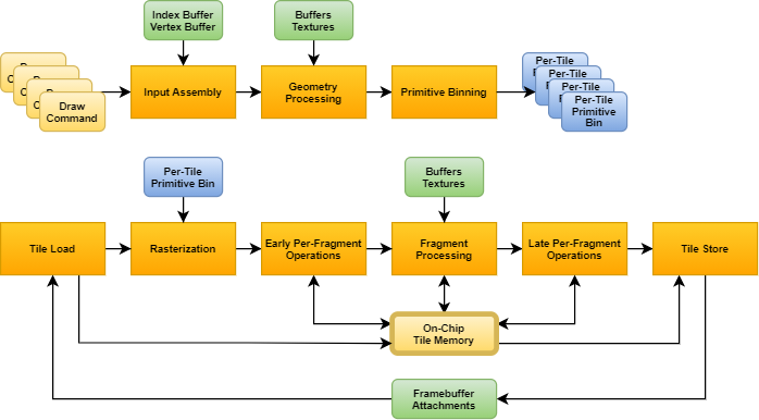
The VK_DEPENDENCY_BY_REGION_BIT provides the unique ability to leverage that by minimizing the scope and therefore the performance impact of pipeline barriers in specific scenarios. In particular, one common example is a fragment-shader-to-fragment-shader dependency, or any other dependency where only fragment processing stages are involved, and the dependency itself is local in framebuffer space (e.g. because fragment operations in subsequent draws only depend on the results of fragment operations in previous draws on a pixel-local basis). In such cases VK_DEPENDENCY_BY_REGION_BIT avoids having to wait for the completion of all previous per-tile fragment processing steps.
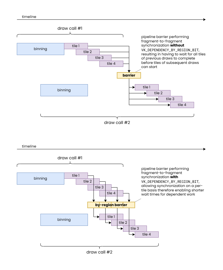
While it can already be seen that this could allow the same workload to be completed faster if there are sufficient processing units available on the GPU, it provides an even more important benefit. TBR GPUs operate on a per-tile basis to optimize framebuffer accesses. This is achieved by keeping framebuffer data in fast on-chip tile memory for the duration of the processing of a tile. However, getting that data on chip (tile load) and then writing back the final results (tile store), when needed, is still very expensive, therefore TBR GPUs can benefit significantly whenever more workload can be crammed in the same per-tile pass, which also explains why Vulkan originally introduced the concept of render passes.
In case of our specific example of a fragment-to-fragment dependency, it is easy to demonstrate how VK_DEPENDENCY_BY_REGION_BIT can avoid redundant tile load/store operations even on a small TBR GPU with a single shader core.
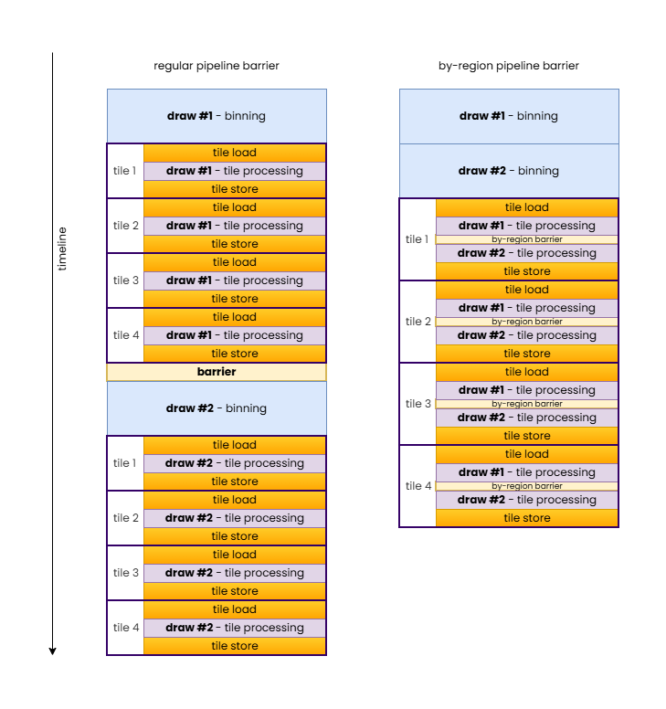
In summary, VK_DEPENDENCY_BY_REGION_BIT allows inserting local fragment-to-fragment pipeline barriers while still allowing TBR GPUs to merge the draws into a single hardware render pass.
Image layouts
We arrived at the most important topic that motivated the creation of this article. Image layouts are one of the most misunderstood features of Vulkan among developers. Developer frustration stemming from this misunderstanding culminated in the attempt to effectively “deprecate” image layouts through the VK_KHR_unified_image_layouts extension, at least to the extent that simple rendering applications can pretty much avoid having to worry about image layouts and image layout transitions in most cases. Our goal is to better explain the rationale behind Vulkan image layouts, why they remain relevant, particularly for advanced use cases crossing device IP block boundaries, and how to use them effectively.
The number one misconception about image layouts is that the application has to track them, therefore it comes with inherent and unavoidable complexity and run-time cost. We will see that, except in a few specific scenarios, applications never have to track image layouts. But let’s step back a bit first and discuss what image layouts are and what they represent…
Image layouts were introduced in Vulkan to enable the application to instruct the driver the type of usage to optimize the physical representation of an image subresource for. This typically translates to the driver deciding what types of image compression schemes it should enable or whether some sort of decompression or compression/resummarization operation it needs to perform when transitioning the image layout of image subresources. We will discuss some types of compression schemes where image layouts have an effect, but it is worth noting that image layouts are not necessarily always about compression, there are other ways image layout transitions may transpose the physical in-memory representation of an image subresource or any metadata associated with it.
Possible values for the API image layout include the following:
VK_IMAGE_LAYOUT_UNDEFINED– indicates that the image subresource is not in any specific image layout (yet) therefore the driver should make no assumptions about its current contents or physical representation (as we will see, this image layout is particularly interesting and enables certain optimization opportunities)VK_IMAGE_LAYOUT_GENERAL– indicates that the image subresource is in an effective hardware image layout that allows using the image in any fashion as otherwise allowed by the operation itself and the image creation parametersVK_IMAGE_LAYOUT_<usage>_OPTIMAL– image layouts with theOPTIMALsuffix indicate that the image subresource is in an effective hardware image layout optimized for a specific usage (e.g.READ_ONLY_OPTIMAL) and cannot be used in any other fashion while being in this layoutVK_IMAGE_LAYOUT_<usage>– image layouts specifying a particular use without theOPTIMALsuffix indicate that the image subresource is in an effective hardware image layout compatible with that specific use (e.g.PRESENT_SRC) and is the naming convention used by image layouts that are specific to a particular use that is not covered by theVK_IMAGE_LAYOUT_GENERALlayout
Over time, all sorts of use case specific and special purpose image layouts have been added to the API whenever a new type of image usage came along that could potentially benefit from optimized or otherwise specific in-memory representation.
Note that we intentionally use the term “image subresource” here, as it’s not really the image, as a whole, that has a corresponding current image layout, but individual mip levels and layers of an image, i.e. its subresources. Therefore at any given time every single mip level and every single layer within that mip level can have its own effective hardware image layout. The addition of the “effective” qualifier and using the term “hardware image layout” is also intentional, as there may not be a one-to-one correspondence between VkImageLayout values and corresponding physical representations, i.e. effective hardware image layouts. In practice, different GPUs, even ones from the same vendor, but from different hardware generations, may end up mapping the same VkImageLayout value to different effective hardware image layouts, and the set of VkImageLayout values mapping to the same effective hardware image layout may also vary across implementations. As an example, VK_IMAGE_LAYOUT_GENERAL and VK_IMAGE_LAYOUT_SHADER_READ_ONLY_OPTIMAL both map to the same fully uncompressed effective hardware image layout on AMD’s first GCN architecture for all non-multisampled color images, but the same is not true for later GCN generations, or for depth and multisampled images.
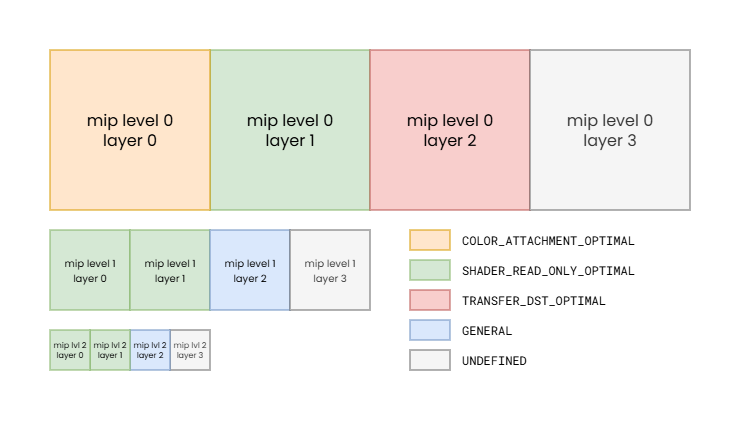
Note: while such variation of image layouts across individual image subresources is rare, it demonstrates that image layout state can be changed for each image subresource individually.
The mapping between API image layouts and effective hardware image layouts therefore is subject not just to the specific GPU architecture, but also to the creation parameters of the image. The available set of effective hardware image layouts, for example, can vary based on the used image tiling (linear or optimal), whether the image is multisampled, what usage flags were specified, etc.
As a trivial example, if an image is created with only the VK_IMAGE_USAGE_COLOR_ATTACHMENT_BIT usage flag specified, then the driver has the freedom to map both VK_IMAGE_LAYOUT_COLOR_ATTACHMENT_OPTIMAL and VK_IMAGE_LAYOUT_GENERAL to the same effective hardware image layout optimized for color attachment use, as the image cannot be used for everything else. However, the same may not be true if VK_IMAGE_CREATE_ALIAS_BIT is also specified when creating the image.
The VkSharingMode can also affect the mapping, as it controls whether the driver can assume exclusive access to the image from queues of the queue family currently owning them, or whether it may be simultaneously accessed by queues from different queue families with potentially different hardware capabilities, as discussed later in this article. Hardware capabilities are the key here, as different queue families, or even different hardware units serving the functionalities provided by a given queue family, such as the texturing units and ROPs of the GPU may not have the same capabilities when it comes to interpreting the data in memory.
Everything sounds simple if one thinks about images as simple 1/2/3-dimensional arrays of individual raw texel values, but the physical reality is often far from the good old pitch-linear image representation. But even the most basic feature of GPUs called texture tiling/swizzling breaks that, whereas the actual texels are not stored in pitch-linear fashion but rather often assembled into recursive hierarchies of tiles arranged physically in memory following the Morton order or other similar order optimized for spatial locality. It’s easy to see that even choosing the optimal image tiling mode for a given GPU and image may come with compromises, as one layout may be optimal for texturing but not necessarily ideal for color attachment use, and it’s also possible for some image tiling modes to be entirely incompatible with one or more hardware blocks within the GPU, therefore the driver often has to make compromises in the physical representation already due to the set of image usages that the application requested.
But it’s not just the order of the individual texels within an image subresource that can vary. Images often have additional meta-surface planes that store information about the compression state or other metadata about the image subresources. These meta-surface planes are typically reduced resolution images whose pixels contain information about the state of the corresponding block/tile (e.g. 4×4, 8×8, or 16×16 pixels) within the actual image subresource. Often, as indicated by such meta-surface planes, the main image plane does not even contain raw texel values but rather something else (such as compressed data) that can only be interpreted together with the corresponding meta-surface plane entries.
In an ideal world, all hardware blocks on the device would be able to interpret and update all such data, both in the main image plane and in any meta-surface planes. However, in practice that is not always feasible due to added die area or performance cost, and there can also be other architectural limitations such as those imposed by cache hierarchy structure and even cache line sizes.
On many recent GPUs, sticking with traditional graphics and compute only workloads may allow using hardware units that share the “same language” therefore can all interpret and update the same data formats (i.e. what VK_KHR_unified_image_layouts promises) without any (or at least not too many) compromises. The same may not be true everywhere, especially when you add other hardware components to the picture such as DMA engines, video codec engines (both present on contemporary graphics cards), or external device interop. The fact that VK_KHR_unified_image_layouts still kept the VK_IMAGE_LAYOUT_PRESENT_SRC_KHR image layout shows that we can have non-orthogonality just trying to “speak” with the display engine.
So why bother with such meta-surface planes at all? Well, performance. The compression schemes and other metadata information that these meta-surface planes enable can often provide double-digit percentage performance improvements on real-world applications, so obviously GPU architectures take advantage of them to the extent possible. Then why not support them everywhere? Sometimes it would simply not be feasible from an architecture or die area perspective, as eluded to earlier. Sometimes it just doesn’t make sense as the compression scheme or metadata is only relevant to specific operations. Sometimes, like in the case of interop with an external device (such as a camera, capture card, etc.) coming from a different vendor, it’s just not possible at all.
Image layout transitions, therefore, enable performing (typically in-place) transformation of the data in the main plane and the meta-surface planes of the image (such as decompression) to make the image subresource’s in-memory representation compatible with a different use.
Common image compression schemes
Fast clears
The history of “fast clears” goes a long way back, so many are probably familiar with the concept that framebuffer attachment clears are fast and preferred to be done, even if the entire framebuffer is intended to be overwritten, as they can also speed up subsequent rendering. But how exactly is that achieved?
The simplest solution is to use a small meta-surface plane that has exactly one bit for each block/tile of the actual image data that marks whether the block is “fast cleared” (1) or not (0). This enables clearing a framebuffer attachment by simply setting all bits of this meta-surface plane, without even having to touch the main image plane, therefore saving a significant amount of memory bandwidth. Furthermore, when rendering to the attachment, the ROP can just look at the meta-surface plane and avoid having to load any image blocks into the cache if they are in the “fast cleared” state, providing additional memory bandwidth saving even during rendering.
All of this requires though that the ROP is able to load and interpret the meta-surface plane and it knows the clear color/value. That may be too much complexity to add to the texture units, may involve additional indirections, and increase cache storage requirements. Therefore, many GPUs did not even attempt to support accessing such “fast cleared” images. Instead, the appropriate image layout transition (e.g. from VK_IMAGE_LAYOUT_COLOR_ATTACHMENT_OPTIMAL to VK_IMAGE_LAYOUT_SHADER_READ_ONLY_OPTIMAL) “decompresses” (eliminates) the fast clear by actually writing out the clear color/value to the texel blocks/tiles of the main image plane that are still marked as “fast cleared”. This may still be much faster than not using fast clear at all, as the performance benefits are still there during the rendering to the image as an attachment, and at the point of the image layout transition there may not even be any more texel blocks/tiles in the “fast cleared” state.
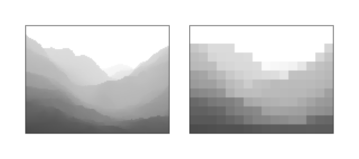
The example shows a 64×64 8-bit RGBA color attachment image using a fast clear meta-surface with 1 bit per 8×8 block/tile.
Note that the main image plane (top left, total size: 16 kilobytes) may still have uninitialized data in the 8×8 blocks/tiles that were not rendered to after the fast clear, as indicated by the 1 values in the fast clear meta-surface plane (bottom left, total size: 8 bytes), but combined with the known fast clear value (transparent black in the example) the effective content of the image (right) looks as expected.
The diagram also demonstrates how an image layout transition can decompress fast clears by combining the two planes (left) and the fast clear color to produce the uncompressed image (right).
This technique still exists in various forms on contemporary GPUs, although they are, to some extent, subsumed by more advanced color compression schemes (such as delta color compression) or more specific ones (such as hierarchical-depth, depth plane compression, or specialized multisampled image compression schemes).
Delta color compression
Delta color compression (DCC) is a technique typically used for non-multisampled color images, as depth and multisampled images often use more specialized schemes. It works by applying lossless compression to the texels within a block/tile. While the compressed data is stored within the main image plane, this compression scheme (like most) typically still uses a separate meta-surface plane to store information about the compression state of each block/tile.
On AMD GPUs, it first appeared with the GCN Gen3 architecture, but went through a set of iterations over subsequent GPU architecture generations. While reading DCC compressed images from shaders was supported from the beginning, without the need to decompress (i.e. doing an image layout transition from VK_IMAGE_LAYOUT_COLOR_ATTACHMENT_OPTIMAL to VK_IMAGE_LAYOUT_SHADER_READ_ONLY_OPTIMAL was effectively a no-op), the same was not true for shader writes, so transitioning to the VK_IMAGE_LAYOUT_GENERAL layout still required decompression if the image was created with VK_IMAGE_USAGE_STORAGE_BIT, for example.
| Current image layout | Image usage flags specified at create time | GCN Gen3 | RDNA |
|---|---|---|---|
| GENERAL | COLOR_ATTACHMENT_BIT | SAMPLED_BIT | ✔️ | ✔️ |
| GENERAL | COLOR_ATTACHMENT_BIT | SAMPLED_BIT | STORAGE_BIT | ❌ | ✔️ |
| COLOR_ATTACHMENT_OPTIMAL | COLOR_ATTACHMENT_BIT | SAMPLED_BIT | STORAGE_BIT | ✔️ | ✔️ |
| SHADER_READ_ONLY_OPTIMAL | COLOR_ATTACHMENT_BIT | SAMPLED_BIT | STORAGE_BIT | ✔️ | ✔️ |
GCN Gen3 does not support shader writes to DCC compressed surfaces, therefore it cannot keep the image compressed in the VK_IMAGE_LAYOUT_GENERAL layout if the image was created with VK_IMAGE_USAGE_STORAGE_BIT.
Note that the examples show best case scenarios as actual driver behavior may be different due to interactions with other image creation parameters such as sharing mode, image create flags, etc.
It is also worth looking into what happens when transitioning from an API image layout that maps to an effective hardware image layout not supporting DCC (or, for that matter, any compression scheme) to an API image layout that maps to an effective hardware image layout that does. A natural thought process would be that such an image layout transition would compress the image subregion(s). In practice, that is rarely the case and is more conventional for such image layout transitions to be no-ops, as compression will be added back to the data anyway (e.g. by rendering new content to the color attachment). Performing a compression pass over the image subregion to potentially save some memory read bandwidth on the first read of each block/tile would likely be a net loss anyway.
As time passed and new hardware generations came, DCC comes with fewer and fewer compromises and limitations. Nowadays, even shader writes are supported to DCC compressed images, effectively making most image layouts, even VK_IMAGE_LAYOUT_GENERAL, to be able to retain full DCC, without the need for the image layout transitions to result in a decompression. At least, in theory. In practice, DCC and similar techniques come in many shapes and forms across different GPU vendors and architecture generations, each with their own quirks and compromises, so your mileage may vary.
Hierarchical depth buffer
Depth images can also benefit from plain-old “fast clear” compression, using DCC, or other lossless compression schemes tailored specifically for depth images, but the most interesting depth compression technique is hierarchical depth (or Hi-Z). This is a technique that is almost as old as fast clears, yet it is still very much prevalent. The core idea is that we use a separate meta-surface plane to store for each texel block/tile the minimum and/or maximum depth value within that texel block/tile. This is done by the ROP during the depth write process, therefore it comes with minimal added complexity or memory bandwidth requirements.
Having information about the per block/tile minimum and/or maximum depth values allows the ROP to trivially reject entire blocks/tiles during depth testing if the current depth comparison mode and the incoming triangle’s plane equation indicates so. E.g. if the depth comparison mode is “less than”, but the incoming triangle’s plane equation indicates that for a given block/tile the triangle’s pixels will all have greater depth values than the current per block/tile maximum stored in the Hi-Z meta-surface plane, then no pixels of the triangle with pass the depth test so the entire block/tile of pixels can be dropped without having to perform any per-pixel operation.
The interesting thing about Hi-Z is that, while it can be considered a compression scheme, it doesn’t actually require decompression as the main image plane always contains the full, uncompressed representation of the depth image, unless other compression schemes are also applied. Therefore, an image layout transition from VK_IMAGE_LAYOUT_DEPTH_STENCIL_ATTACHMENT_OPTIMAL to VK_IMAGE_LAYOUT_SHADER_READ_ONLY_OPTIMAL can be a no-op, although, in practice, it will rarely be a no-op, as usually other depth compression schemes are used in conjunction.
However, what happens when an image layout transition is performed e.g. from VK_IMAGE_LAYOUT_GENERAL to VK_IMAGE_LAYOUT_DEPTH_STENCIL_ATTACHMENT_OPTIMAL? In this case it is possible that some other, non-attachment use of the depth image updated some of the depth values, but not the values in the Hi-Z meta-surface plane (as Hi-Z is not relevant anywhere else but during depth testing, it’s unlikely that shader or DMA writes, for example, will also update the Hi-Z values). This is a problem, because the stale values in the Hi-Z meta-surface plane could cause misbehaviors during depth testing.
While it’s also a possibility to disable Hi-Z altogether if the depth image may be written through other means, what usually happens is that the layout transition back to VK_IMAGE_LAYOUT_DEPTH_STENCIL_ATTACHMENT_OPTIMAL “resummarizes” the Hi-Z meta-surface plane’s content, effectively bringing it up-to-date with the main image plane data.
In summary, it can be observed that the effect of an image layout may be any of the following, depending on the image itself, the old and new image layouts specified, and the target GPU architecture:
- No-op, if the effective hardware image layout corresponding to the old and the new API image layouts match on the specific GPU and driver
- No-op, if the new effective hardware image layout does not support the compression scheme and the old one does, but the data in the main image plane itself is not compressed (e.g. Hi-Z)
- Decompression, if the new effective hardware image layout does not support the compression scheme but the old one does, and the data in the main image plane itself is compressed (e.g. DCC)
- No-op, if the new effective hardware image layout supports the compression scheme and the old one doesn’t, and the opposite transition would result in a decompression (e.g. DCC)
- Resummarization, if the new effective hardware image layout supports the compression scheme and the old one doesn’t, and the opposite transition would result in a no-op (e.g. Hi-Z)
Nonetheless, this only considers dual-state compression schemes (the surface is either compressed or decompressed), whereas some compression schemes can have multiple states/levels (e.g. some multisampled image compression schemes are tri-state), and multiple compression schemes may be used in conjunction. So, in practice, image layout transitions can result in combinations of any of the operations listed above.
When you consider all of that, and that the set of effective hardware image layouts and the types of accesses they support can vary across GPUs, even across ones from the same vendor, it is easy to see how much of the actual complexity and implementation divergence is abstracted away by image layouts such that the application does not have to worry about these differences, while also having explicit control over when and what type of image layout transitions should be performed.
Undefined is good
VK_IMAGE_LAYOUT_UNDEFINED deserves its own section, because it enables so many optimization opportunities that even VK_KHR_unified_image_layouts did not attempt to eliminate. This image layout effectively says “I don’t know what layout the image subresource is in but I also don’t care”. This opens up the door for driver implementations to transition the layout of the image subresource without any care for what the main image plane or meta-surface planes may contain.
For example, transitioning from VK_IMAGE_LAYOUT_UNDEFINED to VK_IMAGE_LAYOUT_COLOR_ATTACHMENT_OPTIMAL may be implemented by simply performing a fast clear that effectively moves the image subresource into a well-defined physical layout at a fraction of the memory bandwidth cost of having to touch the main image plane. The same is true in case of transitioning a depth/stencil image to VK_IMAGE_LAYOUT_DEPTH_STENCIL_ATTACHMENT_OPTIMAL. In this case, having specified an old image layout of VK_IMAGE_LAYOUT_UNDEFINED, the driver also doesn’t have to worry about resummarizing the Hi-Z meta-surface, avoiding further performance overhead.
The VK_IMAGE_LAYOUT_UNDEFINED can also be beneficial for TBR GPUs, or other architectures utilizing various types of on-chip storage, as it is sort of the analog of the VK_ATTACHMENT_LOAD_OP_DONT_CARE value used to indicate that a TBR GPUs does not have to load the current data of an attachment image, as the current (old) content in it will not be used. In fact, it might even have a positive effect on the cost of cache control operations in certain circumstances on a sufficiently sophisticated GPU and driver combination.
Tracking image layouts
Before going into why Vulkan applications don’t necessarily have to track the image layouts of individual image subresources, that is often cited as the most annoying and complex problem the existence of image layouts in Vulkan imposes, let’s first ask the more obvious question…
Why do Vulkan image layouts even exist when earlier APIs like OpenGL did not have them, even though the underlying GPUs still had the same problem with compression schemes to deal with?
The short answer is fairly simple: it was all hidden and managed by the drivers. Drivers effectively had to do that dreading image layout tracking and had to automatically insert the appropriate image layout transitions (decompression, resummarization, etc.) when necessary. This was not trivial to do, more so because the driver itself had no contextual information about the application as its writer did, because it only saw the incoming raw API call stream.
This didn’t only involve a lot of complex driver logic that everybody had to pay the run-time cost of, but also came with lost optimization opportunities because the driver could not always guess what would be the best thing to do with limited information. For example, one could think that when a texture is bound in OpenGL, the driver could simply perform the equivalent of a Vulkan image layout transition on the texture to a shader readable effective hardware image layout. But in practice most applications bound textures and other objects only to then bind a different one later before doing any draw calls. This could not only result in unnecessary (and quite costly) decompression operations, but the effects of an unnecessary decompression could also impose a significant performance overhead if subsequent operations could have taken advantage of the memory bandwidth savings of the compression.
Therefore most drivers actually delayed the layout transition up until the last moment, e.g. when a draw was actually issued that is now known to need the image to be decompressed. While also contributing significantly to the so-called “draw-time overhead” the old graphics APIs were famous for, delaying these operations up until the last moment also limited concurrency potential, effectively resulting in longer overall run time.
But even if that would be a cost that developers would be comfortable to suffer if they wouldn’t have to deal with image layouts, the reality is that with today’s GPU-driven and “bindless” workloads it is not even possible for the driver to figure out which resources are going to be used by a draw or dispatch. Therefore image layouts in the API are not only an opportunity to better control the compression schemes and schedule image layout transitions, but a necessity. That is, if we accept our assertion that there will always be hardware units out there that cannot understand all the compression schemes used across the entire GPU or the entire system.
Some Vulkan developers will not be able to avoid tracking image layouts. For example, developers working on drivers emulating legacy APIs on top of Vulkan, such as Zink or Angle will inevitably have to deal with this, at least to some extent, as it is their duty to add back the “driver magic” of a legacy API driver on top of Vulkan, with all the internal complexity and performance cost that comes with it. But if we exclude these types of middleware, there is rarely ever a good reason for a Vulkan application to track the image layout of image subresources, hence the premise that Vulkan image layouts are “the problem” is moot. Let’s see why…
Not tracking image layouts
Tracking the current image layout of subresources is really unnecessary in usual application code, except maybe in very niche situations. An application uses images for specific purposes, therefore it has high-level knowledge about what image layout its subresources should be in at any given time, not through tracking, but inherent from their purpose and expected usage pattern.
In particular, in most cases there is a clear “default image layout” that the application can assume the image subresources are in. Having that knowledge, the application can simply transition the layout of specific image subresources to other image layouts than the default one temporarily, as needed, without any tracking. We will go through a couple of examples to show how this can work in practice.
Plain-old textures
When an image is used for plain-old texturing, it is reasonable to assume everywhere in the application code that the current image layout of all its subresources is VK_IMAGE_LAYOUT_SHADER_READ_ONLY_OPTIMAL. Sure, that won’t be the case initially, as all images are created with the VK_IMAGE_LAYOUT_UNDEFINED layout (we will not consider the VK_IMAGE_LAYOUT_PREINITIALIZED, as that is an uncommon case, but the same applies there). Before being able to texture from the image, the application will anyway have to upload the texture contents to it, which typically will involves e.g. an image layout transition to VK_IMAGE_LAYOUT_TRANSFER_DST_OPTIMAL, a copy to it, then a transition to VK_IMAGE_LAYOUT_SHADER_READ_ONLY_OPTIMAL. Once there, there really isn’t a need to perform further image layout transitions on the image, therefore it’s a reasonable expectation to assume this default image layout anywhere in the code.
The situation is somewhat more complicated if per-subresource texture streaming is used, or if full-on virtual texturing is used through sparse images. However, even in that case, the application only needs to track whether the specific subresource and/or virtual texture tile is loaded or not, which it has to do anyway, but the image layouts can still be assumed without tracking: if the subresource is not loaded yet (or has been evicted), then its image layout is assumed to be VK_IMAGE_LAYOUT_UNDEFINED. When it is loaded, the same process happens as in case of regular texture uploading. If already loaded, the layout can be assumed to be VK_IMAGE_LAYOUT_SHADER_READ_ONLY_OPTIMAL.
Framebuffer attachments
For simple color attachments used during rendering, once again, a default image layout can be assumed: VK_IMAGE_LAYOUT_COLOR_ATTACHMENT_OPTIMAL. If its content does not need to be preserved (quite typical), you’d anyway start your rendering with an image layout transition from VK_IMAGE_LAYOUT_UNDEFINED to VK_IMAGE_LAYOUT_COLOR_ATTACHMENT_OPTIMAL (no matter whether you use dynamic rendering or render passes), but even if you need to preserve the content, you can assume it was left off in the VK_IMAGE_LAYOUT_COLOR_ATTACHMENT_OPTIMAL image layout. No image layout tracking is necessary. The same applies to depth/stencil attachments, except that the default image layout would be VK_IMAGE_LAYOUT_DEPTH_STENCIL_ATTACHMENT_OPTIMAL.
Things get somewhat more complicated when post-processing is involved and you need to temporarily use the framebuffer attachments as textures (or input attachments) in subsequent rendering passes, but tracking should not be necessary here either. Simply transition the attachment image subresources to VK_IMAGE_LAYOUT_SHADER_READ_ONLY_OPTIMAL for the duration of the post-processing passes needing the image as input. Whether you have to transition the image layout back also depends on whether the attachment contents have to be preserved across frames. In most cases it won’t be necessary as the next frame will anyway start with an image layout transition from VK_IMAGE_LAYOUT_UNDEFINED. The application should already have knowledge about which post-processing steps need any attachment as input, and any other policy on where and how long the attachment contents can be accessed.
Sure, things may be less trivial in some cases, such as when a depth/stencil attachment is used as an input texture for post-processing while also being used for depth testing, and therefore one has to use the more exotic image layouts such as VK_IMAGE_LAYOUT_DEPTH_STENCIL_READ_ONLY_OPTIMAL, but the principle remains valid: the default image layout remains the attachment optimal one, except for the duration of operations intending to use the attachment image otherwise.
Shadow maps, reflection maps, etc.
These types of images are not that different from plain-old textures either. By default, the application will assume it can use them when applying shadows/reflections/etc. therefore it’s reasonable to assume them to always be in the VK_IMAGE_LAYOUT_SHADER_READ_ONLY_OPTIMAL default image layout. This only needs to change for the duration of the render-to-texture pass initializing or updating them, which is a trivial temporary and local transition to one of the attachment optimal layouts for the duration of rendering to them.
These types of use cases also highlight the real power of Vulkan image layouts. Thanks to the explicit control, the application can choose which image subresources (individual mip levels and layers) will be updated and only transition those. In traditional APIs, drivers would often have to do a lot of guess work in this process that usually manifested in unexpected performance pitfalls.
Bonus use case
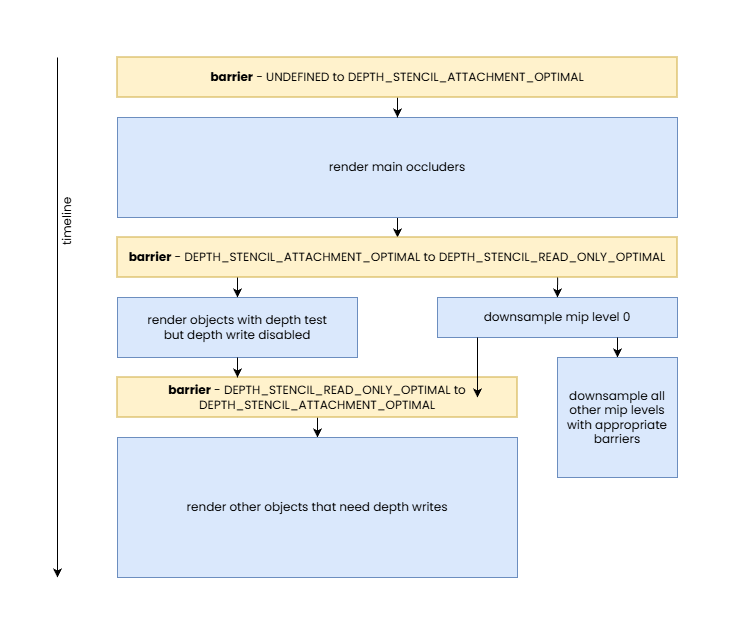
We can see that some developers will still have a skeptical view of the examples we shown here due to their simplicity, so let’s look at a final, more complicated use case: depth buffer used for hierarchical-Z map based occlusion culling while also performing additional rendering with the depth attachment, both read-only and read-write.
In this case we, once again, work with an image used as depth attachment, but one that has mip levels. The base level is generally used as a depth attachment, therefore its default image layout remains to be VK_IMAGE_LAYOUT_DEPTH_STENCIL_ATTACHMENT_OPTIMAL, but for all other mip levels that are normally used only in the occlusion culling passes as input will have a default image layout of VK_IMAGE_LAYOUT_SHADER_READ_ONLY_OPTIMAL.
After the initial render pass, we have to re-build the mip chain. This can be done by transitioning the base level temporarily to VK_IMAGE_LAYOUT_SHADER_READ_ONLY_OPTIMAL, and mip level 1 to VK_IMAGE_LAYOUT_GENERAL, in order to update the latter. If there are further rendering passes that want to use the depth attachment for depth testing, then VK_IMAGE_LAYOUT_DEPTH_STENCIL_READ_ONLY_OPTIMAL can be used for the base level instead, and such rendering passes can even be performed concurrently with the downsampling.
If subsequent rendering passes need to use the depth attachment with depth writes enabled, then obviously that can only happen before or after the downsampling into mip level 1, as otherwise one might encounter data race issues. But such rendering passes can still execute concurrently with the updates of subsequent mip levels of the hierarchical-Z map.
After mip level 1 is populated, it can be transitioned back to VK_IMAGE_LAYOUT_SHADER_READ_ONLY_OPTIMAL, and all subsequent mip levels can be updated by following the steps below for all subsequent mip levels:
- Transition the mip level from
VK_IMAGE_LAYOUT_SHADER_READ_ONLY_OPTIMALtoVK_IMAGE_LAYOUT_GENERAL - Update the mip level
- Transition the mip level from
VK_IMAGE_LAYOUT_GENERALback toVK_IMAGE_LAYOUT_SHADER_READ_ONLY_OPTIMAL
Of course, there are further optimization opportunities for such mip chain update processes which fall outside the scope of this article, but the bottom line is that all of this can be done without ever needing to track image layouts anywhere in the application: all current image layouts are simply assumed and inherent from the high-level application algorithm itself.
It might be a great exercise for the reader to implement the above with Vulkan image layouts, per above, and compare its performance with that of an implementation using a legacy API or an implementation relying on the promises of VK_KHR_unified_image_layouts and using VK_IMAGE_LAYOUT_GENERAL everywhere. If that is still not convincing enough then not sure what would be.
Sharing modes and queue family ownership transfers
We left sharing modes to the end because they have an overarching effect on everything we discussed so far. Vulkan provides two sharing modes that the application can choose from when creating image or buffer resources:
VK_SHARING_MODE_EXCLUSIVE– ranges of buffers or subresources of images created with this sharing mode can only be used by queues of the same queue family at any given time, and queue family ownership transfer barriers need to be used to transfer exclusive ownership of a buffer range or image subresource from one queue family to anotherVK_SHARING_MODE_CONCURRENT– resources created with this sharing mode can be used by queues of any queue family that the resource was created with, requiring no queue family ownership transfers
After a quick look at these modes, developers may ask themselves why would they ever not use the concurrent sharing mode, considering that it sounds simpler. The answer, as usual, is performance. In order to understand the rationale and behavior, it has to be noted that this is yet another acknowledgement of the fact that queues from different queue families can have different hardware capabilities when it comes to being able to interpret compressed image data, from the perspective of cache hierarchies, etc.
In practice, this means that whenever VK_SHARING_MODE_CONCURRENT is used to create a buffer or image, the driver has to assume that any queue from any of the specified queue families may access the resource at any given time. This often results in the driver having to make more conservative compression scheme and cache flushing/invalidation choices, potentially incurring significant performance overhead for all accesses to the resource.
Using VK_SHARING_MODE_CONCURRENT may not have much of an impact if the only queue families the resource is shared across are the compute and graphics queue families often found on devices. These usually have the same (or very similar) capabilities, barring the lack of graphics-related functionality available on compute-only queues. However, the same may not be true when a transfer-only queue family is included that may be implemented using some sort of DMA engine. Such DMA engines often do not understand any of the graphics-specific image compression schemes and they may not use the same cache hierarchy, if any at all. The same is often true for other non-graphics/compute queue families such as the video decode and encode queue families.
For example, we saw earlier that, subject to the used image usage flags and GPU generation, AMD’s DCC image compression scheme can be in effect even if an image subresource is in the VK_IMAGE_LAYOUT_GENERAL layout. However, that may not be the case if the image was created with VK_SHARING_MODE_CONCURRENT and the specified queue families include non-graphics/compute queue families. The situation may even be worse for more graphics-centric compression schemes such as fast clears or Hi-Z, as those are typically not relevant or usable even on a compute-only queue.
This also reveals that even for a given GPU the mapping between API image layouts and effective hardware image layouts is subject to the sharing mode the image was created with, the set of queue families the image is shared across when VK_SHARING_MODE_CONCURRENT is used, or the current queue family having ownership of the image subresource when VK_SHARING_MODE_EXCLUSIVE is used. This is why image layouts do not even attempt to refer to specific effective hardware image layouts.
Therefore, it may not come as a surprise that we advise developers to always use VK_SHARING_MODE_EXCLUSIVE if they seek ultimate performance, although in very specific scenarios even VK_SHARING_MODE_CONCURRENT may come without comprises. The only thing one has to worry about when using VK_SHARING_MODE_EXCLUSIVE is to make sure that the right queue family ownership transfers are performed at the boundaries of sharing resources between queue families.
Of course, it’s possible that on some implementations, with some combination of image creation parameters and some specific image layouts, using VK_SHARING_MODE_CONCURRENT may not have performance consequences. Although even in such cases it should be fine to use VK_SHARING_MODE_EXCLUSIVE, as the only downside is the minimal CPU cost incurred by having to issue queue family ownership transfers which, in such cases, would anyway result in no-op. Therefore the only good reason to use VK_SHARING_MODE_CONCURRENT is when the application actually needs concurrent access to the same buffer range or image subresource in queues created from different queue families (concurrent access from queues of the same queue family are allowed by VK_SHARING_MODE_EXCLUSIVE).
A queue family ownership transfer can be performed as part of a pipeline barrier by specifying different values in the srcQueueFamilyIndex and dstQueueFamilyIndex members of buffer and/or image memory barrier structures. The former specifies the index of the queue family to release ownership from, while the latter specifies the index of the queue family to acquire ownership for.
Interestingly, pipeline barriers containing queue family ownership transfers need to be issued both on the queues of both the source and destination queue family. These correspond to the “release” and “acquire” parts of the ownership transfer operation. While the ownership transfer is issued on both sides, typically at least one of them ends up being a no-op. Why?
Let’s take the example of a DCC compressed image subresource. If ownership is transferred from e.g. the graphics queue family to a queue family that does not “understand” DCC, the “release” part of the ownership transfer operation will result in a DCC decompress operation to ensure that the target queue family will be able to read the data in the image subresource and the “acquire” part will be a no-op. It’s easy to see that the necessary decompression wouldn’t be possible to be performed on the “acquire” part of the pipeline barrier pair, as the destination queue family is not able to interpret DCC compressed data, let alone being able to decompress it.
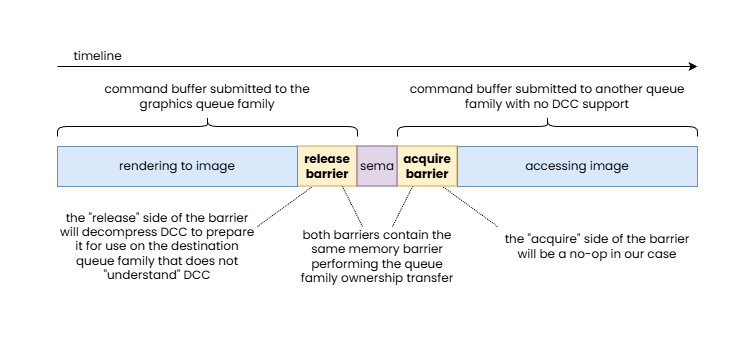
In this example, an image with DCC is handed off to a queue family that is not able to interpret DCC data, therefore the “release” side of the pipeline barrier pair performing the queue family ownership transfer is responsible to perform a DCC decompress.
Another example that is worth looking at is a depth image subresource with a Hi-Z meta-surface plane. Imagine the depth image subresource was updated on the transfer-only queue and now ownership has to be transferred to the graphics queue to use the image as a depth attachment. As we discussed earlier, this may require resummarizing the data in the Hi-Z meta-surface plane, as the main image plane data may no longer be in sync with the Hi-Z data. In this case this most likely can only be performed on the “acquire” side of the pipeline barrier pair, as the transfer-only queue is unlikely to be able to perform such a Hi-Z resummarization pass, while the “release” side will end up being a no-op.
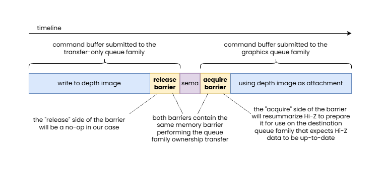
In this example, a depth image updated by a transfer-only queue is handed off to the graphics queue family that expects to use Hi-Z data, therefore the “acquire” side of the pipeline barrier pair performing the queue family ownership transfer is responsible to perform a Hi-Z resummarization.
This is why queue family ownership transfers always come in pairs, as it enables the driver to perform the necessary data transformations on the queue family that can actually perform them, without the application developer having to be aware of which queue family is the suitable one.
Of course, while it is relatively rare, it’s also possible for the two queue families to both support some sort of compression or optimized layout but distinct ones. In such cases it is possible for both the “release” and “acquire” sides of the queue family ownership transfer barrier to have to perform appropriate transformations.
These examples reveal one more thing: queue family ownership transfers may result in an effective hardware image layout transition even if the API image layout remains unchanged. In particular, in the earlier DCC example, the queue family ownership transfer will result in a DCC decompression (an effective hardware image layout transition from “DCC-compressed” to “DCC-uncompressed”) even if both the old and new image layouts were VK_IMAGE_LAYOUT_GENERAL.
Beyond basic sharing mode related use cases, queue family ownership transfers play an important role in advanced applications that share resources across APIs, processes, and devices. In these cases the srcQueueFamilyIndex of the “acquire” side and the dstQueueFamilyIndex of the “release” side of the pipeline barrier pair performing the queue family ownership transfer take one of the following values:
VK_QUEUE_FAMILY_EXTERNAL– refers to a queue that is external to the current Vulkan instance (it’s a queue of another Vulkan or non-Vulkan API queue in the same or a different process) but one that refers to a queue of the same physical device or device groupVK_QUEUE_FAMILY_FOREIGN_EXT– refers to a queue belonging to another device, let that be another GPU or some other device, such as a capture card, camera, network adapter, or anything else
Conclusion
Throughout the article, we went through the key aspects of Vulkan pipeline barriers, provided numerous examples showcasing specific benefits of the Vulkan synchronization model, and attempted to disprove some of the common misconceptions about it. Admittedly, despite the extent of the article, we still couldn’t cover everything in the level of detail they deserve.
Among those misconceptions we tackled, we believe that we also managed to clarify why some of the bold claims implied by the introduction of VK_KHR_unified_image_layouts should be taken with a grain of salt. After all, that extension is a wishful promise that using VK_IMAGE_LAYOUT_GENERAL everywhere (barring the exceptions) will not come with performance compromises. While GPUs have evolved over time, image layouts remain relevant when you look at Vulkan not just as an API for graphics workloads, but an API that exposes functionalities beyond graphics, including access to other hardware components often present on graphics cards, such as video codec engines and DMA engines, and an API that can interact with other external hardware and software stacks.
Our hope is that this article not only managed to explain the underlying behavior of pipeline barriers, but also revealed the rationale behind all of its apparent complexity, enabling the reader to create a better mental model of their function. We believe that this mental model will enable developers to implement more efficient yet simpler Vulkan applications by understanding how they can leverage the high level knowledge they have about their application use cases to issue the appropriate pipeline barriers, and image layout transitions included in them, without adding much, if any, complexity to, or even eliminating existing complexity from their existing code base.